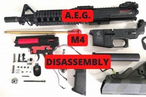
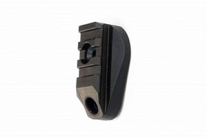
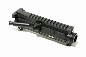
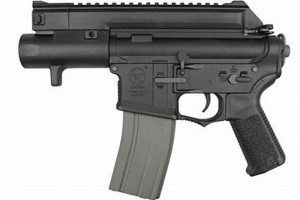
A visual representation of the internal and external components of a specific type of airsoft replica is a detailed illustration. This schematic often includes labeled parts, exploded views, and assembly instructions pertinent to the model being depicted. For example, it might show the precise location of the hop-up unit, the gearbox components, or the external body pieces of an M4-style airsoft rifle.
Access to a thorough visual aid offers significant advantages for airsoft enthusiasts. It facilitates understanding the mechanisms of operation and allows for more informed maintenance, repair, and modification of the equipment. Historically, such visual aids were primarily found in printed manuals; however, digital formats have become increasingly prevalent, offering greater accessibility and detail.
The following sections will explore the different types of these illustrations, their applications in airsoft maintenance and modification, and where to find reliable resources.
Essential Guidance
The following guidance emphasizes the practical application of a detailed schematic for maintenance and modification purposes.
Tip 1: Component Identification. A diagram facilitates accurate identification of individual parts, aiding in correct ordering of replacements or upgrades.
Tip 2: Disassembly and Reassembly. Use a diagram as a reference during disassembly to ensure proper reassembly sequence, preventing mechanical issues.
Tip 3: Troubleshooting. Reference a schematic to pinpoint the location of potential malfunctions within the internal mechanisms.
Tip 4: Upgrade Planning. A visual aid allows for informed decision-making when selecting compatible upgrade components and assessing their integration.
Tip 5: Internal Mechanism Understanding. Study the diagram to gain a deeper understanding of the gearbox and hop-up unit functions.
Tip 6: Spring Replacement. Identify the spring location to facilitate its exchange, a key aspect for adjusting the replica’s power output.
Tip 7: Wiring and Electrical Components. Trace the wiring using a diagram to diagnose electrical problems, such as motor or battery connectivity issues.
Effective application of a schematic empowers informed decision-making and enhances overall maintenance capabilities.
The concluding sections will summarize the core insights.
1. Component identification
The ability to identify specific components within an airsoft M4 replica is directly facilitated by a comprehensive visual representation. Without such a visual aid, locating and naming specific parts, particularly internal mechanisms, can prove challenging. A detailed schematic displays each component, often with labeled callouts, enabling users to accurately distinguish between similar-looking parts such as tappet plates, cutoff levers, and various gears within the gearbox. Accurate identification is critical; for example, a damaged air nozzle must be correctly identified to ensure the proper replacement is ordered, preventing compatibility issues.
Component identification extends beyond simple visual recognition; it provides the basis for effective maintenance and repair. When troubleshooting a malfunction, the schematic enables the user to pinpoint the exact location of the problem component. Furthermore, the schematic is invaluable during disassembly and reassembly, ensuring that each component is correctly positioned. For example, when upgrading the spring, the exploded view illustration in the diagram shows its precise location, preventing accidental damage to surrounding parts during the replacement process. Accurate component identification significantly reduces the potential for errors during repair or modification.
Ultimately, the relationship between component identification and visual schematics underscores the practical utility of the latter. The airsoft M4’s intricate internal design demands a clear reference for effective operation and maintenance. Challenges exist in keeping these schematics up-to-date due to constant product revisions; however, the fundamental benefit of accurately identifying components remains crucial. This identification enables users to progress to more complex tasks.
2. Assembly Reference
A detailed visual representation of an airsoft M4 model serves as a crucial assembly reference for enthusiasts and technicians. Accurate reassembly is vital to ensuring functionality after disassembly for maintenance, repair, or modification.
- Sequence Verification
The diagram provides a clear illustration of the correct sequence for assembling components. This is particularly important for internal gearbox components where improper sequencing can lead to malfunctions or damage. For instance, incorrect placement of the tappet plate or sector gear can inhibit proper cycling and air seal. The schematic eliminates ambiguity by providing a visual guide to the correct order.
- Orientation Confirmation
Many components within an airsoft M4 require specific orientation for proper function. A diagram illustrates the correct alignment of parts such as the hop-up bucking, motor pinion gear, and anti-reversal latch. Failure to properly orient these components can result in reduced performance or complete failure of the replica. The visual representation removes any guesswork, ensuring proper orientation.
- Parts Inventory and Placement
A detailed parts list included within or accompanying the diagram serves as a checklist during reassembly. This helps to ensure that all components are accounted for and correctly placed within the replica. For example, during a gearbox rebuild, having a complete parts list allows the technician to verify that no shims, bearings, or screws are missing before closing the gearbox. Omission of any part may result in immediate malfunctions.
- Torque Specifications and Fastener Placement
Some diagrams include torque specifications for critical fasteners, ensuring proper clamping force and preventing damage to threads or components. Furthermore, they depict the location and type of each fastener, allowing the user to choose the correct screw or bolt for each location. Incorrect fastener selection or improper torque can lead to stripped threads or loose components, negatively impacting performance and longevity.
By providing a visual guide to component sequencing, orientation, inventory, and fastener placement, a detailed schematic greatly facilitates the assembly process. This enables enthusiasts to confidently maintain, repair, and modify their replicas while minimizing the risk of errors that could lead to malfunctions or damage.
3. Troubleshooting aid
A detailed visual representation serves as a valuable aid in the troubleshooting process. When a replica malfunctions, the schematic enables systematic problem diagnosis. By visually identifying individual components and their relationships within the system, a user can isolate the source of a mechanical or electrical failure. For instance, if a rifle is failing to feed BBs, the diagram allows a technician to trace the feeding path, examining the magazine, nozzle, and hop-up unit to pinpoint the obstruction or mechanical failure causing the issue. Without the schematic, this process is significantly more time-consuming and prone to error, especially for individuals unfamiliar with the internal workings of the rifle.
The benefits extend beyond basic fault-finding. A diagram can be used to check electrical components. An electrical diagram showing wiring paths, component locations, and potentially voltage measurements assists in diagnosing electrical issues. A cut or dislodged wire, for example, can be found and corrected through the diagram for troubleshooting. A specific instance includes checking if the motor is receiving power and fixing the wiring.
Visual representations facilitate communication between experienced technicians and less experienced users. The schematic provides a common reference point for describing the problem and potential solutions. While not all users may be able to completely disassemble and repair a replica, the ability to identify components and articulate the malfunction facilitates communication with a technician. Although continuous revisions of models necessitate updating schematics, their function as diagnostic tools remains crucial. This functionality allows better maintenance of replicas.
4. Upgrade Compatibility
Determining the suitability of replacement components within an airsoft M4 model is critical for performance enhancement and equipment longevity. A detailed visual representation significantly aids in evaluating interchangeability and preventing damage from incompatible parts.
- Component Dimensions and Fitment
A schematic offers precise measurements and diagrams of individual components, enabling users to verify the physical compatibility of upgrade parts. For example, gearboxes are typically classified by version (e.g., Version 2). A user considering a new motor will need to ensure it will physically fit within the grip of the M4 replica and match the gearbox type. Discrepancies in dimensions will prevent proper installation and function.
- Gear Ratio and Torque Considerations
Upgrading internal gears requires careful consideration of gear ratios and motor torque to prevent premature wear or system failure. A visual guide shows the number of teeth on each gear and motor orientation, allowing informed decisions on gear selection. Selecting a high-speed motor with a high-torque gear set, for example, would result in inefficient energy usage. Diagrams allow visualization of compatibility between these components.
- Electrical System Load and Compatibility
When installing upgraded motors or batteries, it is essential to assess the electrical system’s ability to handle the increased load. A schematic of the wiring harness, MOSFET (Metal-Oxide-Semiconductor Field-Effect Transistor) and other electrical components permits assessment of current-carrying capacity. Upgrading to an 11.1V LiPo battery, for instance, without upgrading the wiring harness may cause the wires to overheat or damage the MOSFET. Having a clear visual depiction of these components is necessary for ensuring compatibility.
- Hop-Up Chamber and Barrel Integration
Replacing the hop-up chamber or inner barrel influences accuracy and range. Compatibility between the chamber and the barrel is essential for a proper air seal and consistent BB trajectory. Different brands may use proprietary designs, requiring specific components. A visual reference shows the interface between these parts, allowing for verifying compatibility and preventing misalignments or air leaks. Mismatched components will lead to inconsistencies in BB trajectory.
In conclusion, the visual representation serves as a comprehensive reference for assessing component compatibility. Compatibility assessment prevents component failure, improves performance, and increases reliability. The availability of these visuals is helpful, despite ongoing model changes.
5. Internal Understanding
A comprehensive grasp of an airsoft M4’s internal mechanisms is paramount for advanced maintenance, customization, and troubleshooting. A detailed schematic is a crucial resource in developing this comprehension, providing a visual roadmap to the replica’s inner workings.
- Component Relationships
The diagram clarifies the spatial arrangement and functional interdependence of individual parts within the gearbox and other assemblies. Understanding how the piston, gears, and tappet plate interact to propel a BB is essential for diagnosing cycling issues or optimizing rate of fire. For example, observing the relationship between the sector gear and tappet plate helps technicians adjust timing for enhanced feeding. Without that visual, mechanical adjustments may be inaccurate.
- Operational Sequences
A visual representation illustrates the sequence of events during a firing cycle. Observing the movement of the piston head during the compression stroke, the hop-up unit affecting the BB’s trajectory, and the trigger contacts engaging the motor provide a comprehensive overview. This enables users to pinpoint bottlenecks that are limiting performance. This understanding goes beyond static component knowledge; it provides context and insights during dynamic usage.
- Failure Mode Analysis
Detailed schematics help to predict potential failure points based on material properties, stress concentrations, and wear patterns. By understanding how components interact and the forces they endure, users can proactively address weaknesses through preventative maintenance or component upgrades. For instance, observing the stress applied to the piston head during high-speed cycling encourages preventative upgrades to high-impact-resistant components. This improves replica lifespan.
- Modification Planning
Internal knowledge supports effective modification planning. Understanding the impact of changing specific components, such as springs or barrels, on overall performance avoids unintended consequences. A change in the spring tension will result in different performance, making diagram study crucial to modification. The modification plans are more robust when the modifications are applied to a known system.
The insights gained from careful study of these diagrams translates directly into improved maintenance capabilities, targeted upgrades, and a deeper understanding of the interplay between parts. While practical experience remains invaluable, the ability to interpret detailed illustrations provides a foundational advantage for enthusiasts seeking to optimize performance, resolve issues, and extend the lifespan of their equipment. The relationship between the parts, operational sequences, understanding of failure modes, and planning modifications all converge as a holistic study, made possible with a well-detailed visual representation.
Frequently Asked Questions
This section addresses common inquiries related to utilizing detailed schematics of airsoft M4 replicas. The information provided aims to clarify the purpose and application of these diagrams in maintenance, modification, and troubleshooting.
Question 1: Where can reliable representations be located?
Reputable airsoft parts retailers and manufacturers often provide detailed schematics on their websites or within product manuals. Online airsoft communities and forums may also host user-generated diagrams; however, the accuracy of these sources should be verified against official documentation whenever possible.
Question 2: How does one interpret the information conveyed in these diagrams?
Visual representations typically employ exploded views and labeled callouts to identify individual components and their relative positions. Understanding basic mechanical and electrical principles is beneficial, though the diagrams themselves often provide sufficient context for most tasks. Referencing multiple diagrams and consulting online resources can aid in deciphering complex assemblies.
Question 3: Are these representations universally applicable across all M4 variants?
No, differences exist between manufacturers and specific models. Schematics are generally specific to a particular brand and version of the M4 replica. Attempting to apply a diagram intended for one model to another may result in incorrect assembly or damage to components.
Question 4: What tools are needed to effectively utilize these schematics for maintenance and repair?
Basic hand tools such as screwdrivers, hex keys, pliers, and a soldering iron (for electrical work) are typically required. A well-lit workspace and a parts tray to organize removed components are also recommended. Specific tasks may necessitate specialized tools such as spring compressors or gearbox opening tools.
Question 5: What are the potential risks associated with disassembling an airsoft M4 based solely on a diagram?
Disassembling an airsoft M4 carries inherent risks, particularly for individuals unfamiliar with its internal mechanisms. Improper handling of components, incorrect reassembly, and the use of incompatible parts can result in malfunctions, damage, or personal injury. Adherence to the diagram and consulting online resources is crucial to reducing these risks.
Question 6: How frequently are these diagrams updated to reflect changes in replica design?
The frequency of updates varies depending on the manufacturer and the rate of product revisions. It is advisable to seek the most recent version of the schematic available and to cross-reference information with other sources to ensure accuracy. Product changes may require re-evaluation.
The above answers should cover any frequent or common questions associated with these types of visuals.
The next section will provide a summary of the points discussed.
Conclusion
The preceding exploration detailed the applications of a schematic for the airsoft M4 platform. The analysis encompassed component identification, assembly reference, troubleshooting assistance, compatibility verification, and enhancement of internal understanding. This visual aid supports informed decision-making, facilitates maintenance and repair, and minimizes the risks associated with complex modifications.
Given the intricate nature of the airsoft M4 and the continuous evolution of its design, reliance on accurate, up-to-date schematics is paramount. The ability to interpret and apply the information contained within such a illustration contributes significantly to the longevity and performance of the equipment. Therefore, diligent study and careful application of these resources are essential for any serious enthusiast or technician in this field. Access and understanding of the visual aids enable more efficient repairs and lower downtime.


