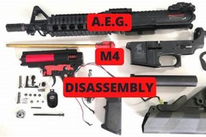
A visual representation illustrating the components of a specific type of airsoft rifle is a crucial resource. This schematic typically includes labeled depictions of internal and external elements, assisting in identification and understanding the relationships between various pieces. For instance, a user can examine such a chart to locate and identify the hop-up unit, gearbox, inner barrel, and various receiver components within the rifle’s assembly.
The availability of detailed visual guides is significantly beneficial for maintenance, repair, and customization efforts. These aids promote accurate reassembly after disassembly, allow for efficient troubleshooting of malfunctions, and facilitate the selection of appropriate upgrade parts. Historically, such diagrams were often found in printed manuals. The proliferation of online resources has led to greater accessibility, with many manufacturers and retailers providing these tools digitally.
Understanding the intricacies of component identification and assembly is fundamental to effective airsoft rifle maintenance. This knowledge base forms the foundation for advanced topics such as performance optimization, custom builds, and the diagnosis of complex mechanical issues. The following sections will delve into specific aspects of airsoft rifle mechanics, component function, and common repair procedures.
Essential Insights for Component Identification
This section provides practical advice for effectively using visual guides depicting the components of a specific type of airsoft rifle.
Tip 1: Reference Multiple Sources: Consult several schematics from different manufacturers or retailers. Variations in design or nomenclature may exist, and cross-referencing aids comprehensive understanding.
Tip 2: Prioritize High-Resolution Images: Clear, detailed visuals are essential for accurate component identification. Blurry or low-resolution representations hinder effective analysis.
Tip 3: Focus on Exploded Views: These representations display components separated but in spatial relation, facilitating comprehension of assembly order and interconnections.
Tip 4: Utilize Interactive Diagrams: Some online resources offer interactive charts allowing users to zoom, rotate, and click on individual components for detailed information.
Tip 5: Pay Attention to Part Numbers: Where available, component part numbers are invaluable for accurate identification and ordering replacements.
Tip 6: Cross-Reference with User Manuals: Many manufacturers provide component charts in their user manuals. These are often model-specific and highly accurate.
Tip 7: Consider Compatibility Charts: When upgrading or replacing components, refer to compatibility charts to ensure proper fit and function within the rifle’s system.
These insights emphasize the necessity of meticulous visual analysis for effective repair and customization. A thorough understanding of the rifles components ensures successful maintenance and enhances performance.
The following sections explore common maintenance tasks and troubleshooting strategies, building upon the foundational knowledge presented here.
1. Component identification
Effective utilization of visual guides depicting the internal structure of a specific type of airsoft rifle requires a foundational understanding of component recognition. Proper identification is the cornerstone of informed maintenance, repair, and upgrade procedures.
- Nomenclature Standardization
Accurate component recognition hinges on familiarization with standard terminology. Though variations may exist between manufacturers, core components such as the hop-up unit, gearbox, and inner barrel maintain consistent designations. Misidentification due to terminological ambiguity can lead to incorrect part selection and subsequent performance issues. For example, confusing the nozzle with the tappet plate during replacement may cause feeding malfunctions.
- Internal vs. External Components
Classification of parts as either internal or external is a critical distinction. Internal components, such as gears and pistons within the gearbox, necessitate specialized tools and knowledge for access and manipulation. External components, including the outer barrel and stock, typically offer easier access and replacement. Attempting to replace an internal component without proper disassembly knowledge can result in damage to the airsoft rifle.
- Model-Specific Variations
The specific type of airsoft rifle encompasses a broad range of models, each potentially featuring unique component designs and configurations. A visual guide intended for one model may not accurately reflect the component arrangement of another. Consulting model-specific charts or diagrams is crucial to ensure accurate identification. For instance, variations in hop-up unit design across different rifle models can impact compatibility with aftermarket buckings.
- Material Composition and Function
Identifying the material composition of a component provides insights into its durability and intended function. Metal components generally offer greater strength and resistance to wear, while plastic parts prioritize weight reduction and cost-effectiveness. Recognizing that the piston head is polymer while the gears are metal provides insight to stress areas of the component within the gearbox. The material characteristics informs component selection during upgrades, balancing performance with longevity.
The ability to accurately identify and categorize the numerous components within a specific type of airsoft rifle is indispensable for users engaged in any form of maintenance, repair, or modification. The knowledge fosters informed decision-making, minimizing the risk of damage and maximizing the effectiveness of interventions. Visual guides serve as the primary tool for facilitating accurate component recognition, provided they are utilized in conjunction with a thorough understanding of component nomenclature, classification, and model-specific variations.
2. Assembly sequence
The assembly sequence, as depicted in a visual chart of a specific airsoft rifle, represents a critical pathway for proper rifle function. The schematic is not merely a collection of components; it illustrates their relationship within a structured construction process. Deviating from this sequence can directly result in malfunctions, damage to parts, or complete operational failure of the rifle. The order in which components are connected, aligned, and secured is paramount. For instance, improper seating of the hop-up unit before securing the inner barrel can lead to air leaks and inconsistent projectile velocity. The diagrammatic representation, therefore, provides a visual algorithm for successful rifle assembly or reassembly after maintenance.
Real-world examples highlight the practical significance of adhering to the indicated sequence. Incorrectly installing the gearbox into the lower receiver prior to correctly positioning the motor grip can place undue stress on internal wiring, potentially causing shorts or damaging the motor itself. Similarly, failing to properly align the upper and lower receivers during assembly can impede the charging handle’s functionality or prevent the magazine from seating correctly. Each step within the sequence is interdependent, and errors early in the process often compound, leading to more significant issues downstream. The illustrated guide acts as a proactive measure, mitigating risks associated with ad hoc or uninformed assembly attempts. The diagram is thus an essential tool for both novice and experienced airsoft rifle users.
In summary, the assembly sequence within an exploded view serves as an indispensable roadmap for maintaining and restoring a specific type of airsoft rifle to operational status. Understanding and meticulously following the charted process is essential to avoid mechanical failures, ensure proper functionality, and prolong the lifespan of the rifle. Challenges arise when the diagram is unclear or incomplete, necessitating consultation of multiple sources or seeking expert advice. The assembly sequence, as visually represented, is fundamentally linked to the overall utility and value of an component chart.
3. Troubleshooting aid
A visual representation detailing the individual components of a specific airsoft rifle serves as an essential resource for diagnosing malfunctions. The diagrammatic portrayal facilitates identification of potential problem areas by providing a clear visualization of component interrelationships and spatial arrangement. When a malfunction occurs, users can reference the diagram to isolate specific components or systems as potential sources of the issue. For instance, a feeding problem may prompt inspection of the magazine, hop-up unit, and nozzle as depicted in the chart to pinpoint the cause.
The functionality of the diagram as a troubleshooting tool extends to assessing component condition. By comparing the physical appearance of parts with their representations in the chart, users can identify signs of wear, damage, or misalignment. A damaged piston head, a cracked gearbox shell, or a misaligned hop-up bucking are conditions visually discernible using the schematic as a reference. This comparative analysis aids in determining whether replacement or adjustment is necessary. Furthermore, the schematic clarifies the disassembly and reassembly process, enabling users to access and inspect internal components systematically. Omission of these details increases the likelihood of incorrect diagnosis, leading to unnecessary part replacements or exacerbation of the problem.
In conclusion, the effectiveness of a visual reference chart as a troubleshooting tool hinges on its accuracy, detail, and ease of interpretation. Properly constructed charts enable efficient problem diagnosis, minimize the risk of component damage during disassembly, and facilitate accurate ordering of replacement parts. Challenges arise when diagrams are incomplete, ambiguous, or fail to reflect model-specific variations, rendering them less effective as troubleshooting aids. The availability and diligent use of comprehensive component illustrations are therefore central to maintaining and repairing this specific type of airsoft rifle.
4. Upgrade planning
Effective planning for upgrades to a specific type of airsoft rifle necessitates a detailed understanding of the rifle’s internal mechanics. Visual guides depicting components are integral to this process, providing the necessary information for informed decision-making. The component chart acts as a blueprint, allowing users to visualize the relationships between different parts and predict the impact of alterations. For instance, upgrading the inner barrel requires knowledge of its length and diameter, information readily available on the diagram. Without this information, compatibility issues and performance degradation may arise. Understanding the relationship helps identify potential bottlenecks and optimize upgrade choices. The schematic thus serves as a vital resource in the preliminary stages of upgrading.
Real-world applications underscore the utility of schematics for upgrade purposes. Installing a new motor, for example, demands consideration of its compatibility with the existing gearbox and battery. A detailed chart enables users to assess the gearbox gear ratio and recommend the appropriate battery voltage for the new motor. Moreover, it assists in the identification of any necessary modifications to the motor cage or wiring. Failure to account for these factors can result in premature motor failure or damage to other internal components. Similarly, upgrading the hop-up unit requires an understanding of its interface with the inner barrel and magazine. The chart illustrates the positioning of these components, facilitating the selection of compatible aftermarket parts. Accurate component identification is crucial for mitigating compatibility issues and maximizing the effectiveness of upgrades.
In summary, effective upgrade planning is contingent upon a thorough comprehension of the system as a whole. Component charts are essential tools for acquiring this understanding, providing a clear visualization of component interactions and spatial constraints. The ability to identify parts, understand their relationships, and anticipate the impact of modifications is pivotal to a successful upgrade. While other sources of information, such as user reviews and online forums, can be valuable, the accurate visual representation within the diagram remains the foundational resource for all upgrade-related decisions. The challenge arises when the provided schematic lacks sufficient detail or accuracy, hindering the upgrade process.
5. Part number reference
Within the context of airsoft rifle component schematics, the inclusion of part numbers is a critical element. These numerical or alphanumeric identifiers provide a standardized method for accurately specifying and sourcing individual rifle components. The reference allows for precise communication between users, technicians, and retailers, minimizing errors in ordering and ensuring compatibility.
- Precise Component Identification
The primary function of a part number is to unambiguously identify a specific component. This is particularly important given the potential for subtle variations in design or functionality across different airsoft rifle models or manufacturers. The code facilitates accurate differentiation, ensuring that the correct replacement or upgrade part is selected. Example: A specific piston head design may have a unique identifier, allowing for its precise ordering even when multiple visually similar options exist.
- Facilitating Parts Procurement
The use of component codes streamlines the parts ordering process. Retailers and manufacturers utilize these identifiers to catalogue their inventory, enabling users to quickly locate and purchase the required components. Without such a reference, the ordering process would rely heavily on visual matching or descriptive terminology, increasing the risk of errors. Example: A code printed on a component schematic can be directly entered into an online parts database to display the specific part for sale.
- Ensuring Compatibility
The code provides a means to verify component compatibility. Replacement or upgrade parts must be compatible with the existing rifle system to function correctly. A part number allows users to cross-reference compatibility charts or consult with technical resources to confirm that a selected component is suitable for their specific airsoft rifle. Example: A user wishing to upgrade their gears can use the code of the original components to find compatible aftermarket options, consulting manufacturer specifications to ensure proper fitment and function.
- Documentation and Traceability
The inclusion of component codes within a chart supports documentation and traceability efforts. Technicians can use these identifiers to record repairs or modifications performed on a rifle, enabling future maintenance to be conducted more efficiently. Furthermore, the codes facilitate tracking the origin and specifications of individual components, which can be valuable for warranty claims or product liability investigations. Example: A technician repairing a rifle can document the codes of replaced components, creating a detailed service record for future reference.
The inclusion of comprehensive, accurate part numbers within component charts significantly enhances their utility. These identifiers are not merely labels; they represent a critical link between the visual representation of a component and its physical procurement and application. Therefore, schematics that integrate robust referencing are more valuable to users seeking to maintain, repair, or upgrade their rifle.
Frequently Asked Questions
This section addresses common queries regarding visual representations of airsoft rifle components, clarifying their usage and benefits.
Question 1: Why are detailed component visualizations necessary?
Detailed schematics enable precise identification, facilitating accurate maintenance and repair. They serve as visual guides for understanding component relationships within the rifle.
Question 2: How does one interpret an exploded view effectively?
Exploded views present components separated but in their relative spatial positions. This arrangement illustrates the assembly sequence and interconnection of parts.
Question 3: Where can reliable component schematics be found?
Reputable sources include manufacturer websites, authorized retailers, and established airsoft community forums. Cross-referencing multiple sources is advisable.
Question 4: What is the significance of part numbers within the component chart?
Part numbers provide a standardized method for identifying and ordering specific components. Their use minimizes errors in procurement and ensures compatibility.
Question 5: Are component diagrams model-specific?
Yes, component arrangements and part designs vary across models. It is essential to use schematics specific to the rifle in question.
Question 6: How can a component layout be used for troubleshooting?
The visualization facilitates identification of potential problem areas and assessment of component condition. Parts can be compared to their representations for signs of wear or misalignment.
Accurate component identification and assembly knowledge are crucial for maintaining and upgrading airsoft rifles. The chart serves as a valuable tool, but should be complemented by practical experience and expert consultation when necessary.
The subsequent section will delve into common maintenance procedures, building upon the information presented here.
Conclusion
The preceding discussion has elucidated the multifaceted utility of the visual representation detailing components of a specific type of airsoft rifle. Key areas examined include component identification, assembly sequence, troubleshooting assistance, upgrade planning, and the significance of part number references. This exploration has underscored the importance of these visual aids in enabling informed maintenance, repair, and modification of the equipment.
Proficient utilization of component charts empowers airsoft rifle users to maintain their equipment effectively and safely. Continued advancements in schematic design and accessibility promise to further enhance the user experience. The accurate visual portrayal remains a cornerstone for responsible ownership and operation of this type of specialized equipment, fostering a culture of informed maintenance and responsible performance enhancement.


