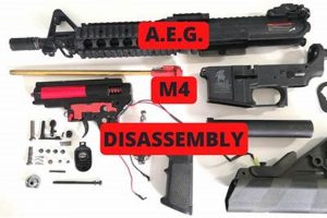
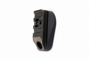
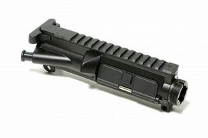
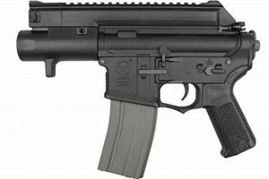
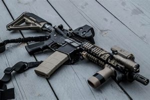
A visual representation illustrating the individual components and their respective locations within a replica M4 rifle used in airsoft sports. This schematic serves as a key for understanding the intricate construction of the airsoft gun, much like blueprints for real firearms, but adapted for the specific mechanics and materials used in airsoft versions. For example, such a depiction would clearly show the placement of the hop-up unit, gearbox, inner barrel, and various external parts in relation to one another.
Understanding the configuration of components allows for effective maintenance, troubleshooting, and performance enhancement of the equipment. Having access to this visual tool facilitates the identification of broken or worn parts, aiding in their replacement or repair. Historically, these representations have been essential for airsoft technicians and hobbyists, enabling self-sufficiency in maintaining and modifying their gear. The detailed breakdown allows for safer and more informed customization.
The following discussion will cover the primary internal and external components depicted within these schematics, common upgrade paths, and resources available for accessing detailed diagrams and technical support. This will provide a foundational understanding for those seeking to delve deeper into the mechanics of the airsoft M4 platform.
Tips for Utilizing Component Schematics
The following outlines strategies for effective utilization of component schematics, enhancing understanding and maintenance capabilities of airsoft M4 platforms.
Tip 1: Component Identification. Regularly reference the schematic when disassembling or reassembling the airsoft gun. Precise identification of each part prevents misplacement and ensures proper function.
Tip 2: Troubleshooting Mechanical Issues. When malfunctions occur, cross-reference the diagram with the gun’s symptoms. This visual aid can help pinpoint the location of a problem, such as a jammed magazine release or a misaligned hop-up.
Tip 3: Upgrade Planning. Before installing aftermarket components, carefully study the diagram to understand how the new part interacts with existing mechanisms. Improper installation can cause damage and reduce performance.
Tip 4: Parts Ordering Accuracy. When ordering replacement parts, use the visual representation to confirm the exact part number and version needed. This minimizes the risk of receiving incorrect components.
Tip 5: Custom Modification Visualization. For advanced users, the representation aids in visualizing custom modifications or internal upgrades. By mapping out changes on the diagram, potential conflicts and design flaws can be identified preemptively.
Tip 6: Understanding Exploded Views. Familiarize yourself with exploded views within the schematic. This view separates each component, clarifying its position and relationship to adjacent parts, aiding disassembly and reassembly procedures.
Effective utilization of component schematics facilitates efficient maintenance, accurate repairs, and informed upgrades, ultimately extending the lifespan and enhancing the performance of the airsoft M4 platform.
The following sections will delve into common problems encountered with the airsoft M4 and how a visual breakdown can aid in their diagnosis and resolution.
1. Nomenclature
Accurate part identification is critical for effective communication, maintenance, and modification within the airsoft community. Standardized nomenclature, as presented in component schematics, ensures clarity and minimizes errors when discussing or ordering components.
- Standardized Terminology
Component schematics rely on consistent terminology to label each part accurately. This standardization prevents confusion arising from colloquial or regional variations in part names. For example, what one user calls a “charging handle latch” might be referred to as a “bolt catch” by another; the schematic provides the definitive term, ensuring both parties understand the component in question.
- Part Number Identification
Many component schematics include manufacturer-specific or industry-standard part numbers alongside the descriptive names. These numbers provide a unique identifier for each part, allowing for precise ordering and verification. If a user needs a specific “piston head O-ring,” the part number guarantees that the correct size and material are obtained, regardless of manufacturer variations.
- Diagram Legend
A diagram legend translates symbols, abbreviations, and annotations used within the schematic. Correct interpretation of this legend ensures that the user accurately understands the diagram’s representation of components and their relationships. Understanding the meaning of dashed lines versus solid lines, for instance, can differentiate between components that are mechanically linked versus those that are simply in close proximity.
- Contextual Understanding
Nomenclature within component schematics provides contextual understanding of a part’s function. By including descriptive names like “hop-up bucking” or “anti-reversal latch,” the schematic clarifies the role each part plays within the airsoft gun’s mechanism. This understanding is critical for troubleshooting issues and selecting appropriate upgrade components.
The consistent and precise nomenclature found in component schematics is essential for anyone working on or modifying airsoft M4 replicas. It provides a common language for communication, ensures accurate part identification, and facilitates efficient maintenance and upgrades. Without this standardization, the complexity of the airsoft M4 platform becomes significantly more challenging to navigate.
2. Component Location
The spatial arrangement of individual components within an airsoft M4 replica, as depicted in a schematic, directly influences its functionality and performance. Understanding the specific location of each part is crucial for effective disassembly, repair, and modification. The visual representation serves as a map, allowing technicians and hobbyists to navigate the complex internal workings of the airsoft gun. For example, a detailed schematic will illustrate the precise positioning of the hop-up unit relative to the inner barrel, a critical factor in determining the accuracy and range of the replica. Similarly, the placement of the various gears within the gearbox must be understood to diagnose and rectify issues with firing rate or power.
Knowledge of component location also facilitates the selection and installation of aftermarket parts. Upgrading the motor, for instance, requires an understanding of its physical dimensions and its relationship to the grip and gearbox. Without a clear understanding of the motor’s location, compatibility issues may arise, leading to improper installation or damage to other components. Similarly, replacing the inner barrel necessitates knowledge of its length and alignment within the outer barrel and hop-up unit. Component schematics provide this essential information, allowing for informed decisions and precise execution of modifications.
In summary, the depiction of component location within a schematic is not merely a visual aid but a fundamental tool for anyone seeking to maintain, repair, or upgrade an airsoft M4 replica. Understanding the spatial relationships between parts is essential for diagnosing malfunctions, selecting compatible components, and executing modifications effectively. While schematics may vary in detail and format, their primary function remains the same: to provide a clear and accurate representation of the internal layout of the airsoft gun, enabling informed and efficient maintenance and enhancement.
3. Disassembly Order
Component schematics provide a visual representation of the constituent parts within an airsoft M4 replica; however, an understanding of the correct disassembly order is paramount for safe and effective maintenance and modification. Failure to follow the designated sequence can lead to component damage or personal injury. The diagram serves as a reference point, while the disassembly order acts as a procedural guide.
- Sequential Access
Disassembly order dictates the precise sequence in which components must be removed to access deeper internal mechanisms. For example, attempting to remove the gearbox before detaching the motor and pistol grip will likely damage these components due to constrained access. The sequence provides the necessary steps to prevent forced removal and subsequent damage.
- Spring Tension Management
Many internal components, particularly within the gearbox, are under spring tension. A documented disassembly order provides warnings and procedures for safely releasing this tension, preventing components from ejecting unexpectedly and causing injury. Improper handling can result in lost parts, damaged components, and potential eye injuries.
- Component Interdependence
Certain components are interconnected and rely on each other for structural integrity. The correct disassembly order acknowledges these interdependencies, ensuring that supporting parts are removed before attempting to detach the primary component. For instance, failing to remove the magazine release before attempting to separate the upper and lower receivers can result in damage to the receiver pins or the magazine release mechanism itself.
- Preservation of Alignment
Some internal mechanisms, such as the hop-up unit and inner barrel, require precise alignment for optimal performance. The correct disassembly order preserves this alignment during the process, minimizing the need for recalibration upon reassembly. Disregarding the sequence can disrupt the alignment, leading to decreased accuracy and range.
In conclusion, while component schematics provide a visual inventory of an airsoft M4, adherence to the proper disassembly order is critical for safely and effectively accessing and maintaining these components. Understanding the sequence, managing spring tension, respecting component interdependencies, and preserving alignment are key elements in utilizing the visual reference for practical application.
4. Compatibility
The interchangeability of components within airsoft M4 platforms presents both opportunities for customization and potential pitfalls for the uninitiated. Component schematics offer a crucial visual reference point for determining compatibility, thereby mitigating the risk of mismatched parts and suboptimal performance.
- Standardization Variations
While the airsoft M4 platform adheres to certain industry standards, subtle variations exist between manufacturers. Component schematics highlight these discrepancies, enabling users to identify parts that may not be universally compatible. For example, hop-up units from different manufacturers may have slightly different dimensions or mounting mechanisms, rendering them incompatible with certain receivers. Visual comparison via the schematic can preempt such issues.
- Internal Component Matching
Within the gearbox assembly, compatibility is paramount for proper functioning. Gear sets, pistons, and cylinder heads must be dimensionally compatible to ensure smooth operation and prevent premature wear or failure. Component schematics detail the specific dimensions and configurations of these internal parts, allowing users to verify compatibility before installation.
- External Accessory Interfacing
The airsoft M4 platform is often customized with external accessories, such as sights, grips, and rail systems. Compatibility with these accessories is contingent on the dimensions and mounting points of the receiver and handguard. Component schematics provide information on these dimensions, allowing users to select accessories that are properly aligned and securely attached.
- Upgrade Component Restrictions
Aftermarket upgrade components, while often designed to enhance performance, may introduce compatibility limitations. High-torque motors, for example, may require corresponding upgrades to the wiring harness and battery to prevent electrical overload. Component schematics illustrate the electrical system layout, enabling users to assess the compatibility of aftermarket components with the existing wiring and power source.
The utility of component schematics extends beyond simple parts identification. They are essential tools for navigating the complex landscape of component compatibility, ensuring that modifications and repairs are performed correctly and that the airsoft M4 platform functions optimally. Careful examination of the schematic prior to any component replacement or upgrade is a fundamental step in maintaining the integrity and performance of the airsoft replica.
5. Exploded Views
Exploded views, as incorporated within an airsoft M4 parts diagram, offer a crucial perspective on the assembly and interrelation of components. They go beyond simple representation, providing a layered understanding vital for maintenance, repair, and modification.
- Spatial Clarification
Exploded views delineate the spatial relationships between parts with enhanced clarity. By separating individual components while maintaining their relative positioning, they facilitate a detailed visualization of how parts interact. This is particularly useful in understanding the complex arrangement of gearbox internals, where numerous gears, springs, and pistons must function in precise coordination. For instance, an exploded view can clarify the relationship between the tappet plate, nozzle, and cylinder head, illustrating how their movements synchronize to load BBs and seal the air cylinder.
- Disassembly Guidance
The representation serves as a guide for disassembly, indicating the order in which parts should be removed. The exploded nature inherently suggests the reverse order for reassembly. For example, viewing the trigger assembly in its exploded state clarifies the sequence for disengaging the trigger spring, sear, and trigger contacts, preventing potential damage or misassembly. This is invaluable for novice technicians or those working with unfamiliar airsoft gun models.
- Component Identification
Exploded views enhance the identification of individual components. The visual separation allows for a more detailed examination of each part’s shape, size, and unique features. This is particularly useful for distinguishing between similar-looking parts, such as different types of shims or screws. In instances where a part number is unavailable, the exploded view provides a visual reference for comparison, aiding in the procurement of replacement components.
- Troubleshooting Assistance
They are valuable resources for diagnosing malfunctions. By visually dissecting the airsoft M4 into its constituent parts, potential sources of problems can be more easily identified. For example, if the airsoft gun is experiencing feeding issues, an exploded view of the magazine and hop-up assembly can reveal misaligned components, worn buckings, or obstructed pathways that may be contributing to the malfunction.
In essence, exploded views within airsoft M4 parts diagrams significantly augment the user’s ability to understand, maintain, and modify their equipment. They move beyond a static representation, providing dynamic guidance for disassembly, component identification, and troubleshooting. Their integration into parts diagrams represents a crucial tool for both novice and experienced airsoft enthusiasts.
6. Upgrade Points
Airsoft M4 parts diagrams facilitate the identification of specific areas amenable to performance enhancement. The diagram functions as a visual roadmap, delineating individual components and their interrelationships, thereby highlighting potential upgrade points. These points are typically components that, when replaced with higher-quality or modified versions, yield measurable improvements in the airsoft gun’s performance characteristics, such as range, accuracy, rate of fire, or durability. For example, a diagram will clearly indicate the location of the hop-up bucking, a small rubber component that significantly impacts BB trajectory. Identifying this as an upgrade point allows the user to research and install aftermarket buckings designed for improved air seal and more consistent backspin.
The consideration of upgrade points within the context of a parts diagram allows for a systematic approach to performance enhancement. Instead of randomly replacing components, the diagram encourages a targeted strategy, focusing on areas where upgrades are likely to have the most significant impact. The diagram also aids in ensuring compatibility between upgrade components and existing parts. For instance, upgrading the motor may necessitate a corresponding upgrade to the battery and wiring harness to handle the increased power draw. The diagram allows for the identification of these related components, preventing potential compatibility issues and system failures. Another example is the spring guide, a component directly impacting the replica’s FPS; the diagram helps determine which spring guide is more suitable for specific configuration.
In conclusion, the connection between upgrade points and these visual aids enables informed decision-making and efficient resource allocation in the pursuit of enhanced airsoft M4 performance. The utilization of a diagram facilitates a structured approach to upgrading, minimizing the risk of incompatible parts and maximizing the potential for achieving desired performance improvements. The diagrams’ contribution is essential in effectively planning and executing upgrades.
7. Troubleshooting
The process of identifying and resolving malfunctions within an airsoft M4 platform is significantly enhanced by the availability of a comprehensive component schematic. The schematic serves as a visual reference, allowing for a systematic approach to diagnosing and rectifying issues that may arise during operation.
- Component Identification for Fault Isolation
A schematic allows for accurate identification of individual components, facilitating the isolation of the source of a malfunction. For example, if the airsoft gun fails to feed BBs, the diagram allows for quick identification of the magazine, hop-up unit, and nozzle as potential points of failure. This eliminates guesswork and allows for targeted inspection of the relevant components.
- Understanding Mechanical Interdependencies
The diagram illustrates the mechanical relationships between different components, allowing for the identification of cascading failures. If the airsoft gun exhibits a reduced rate of fire, the diagram can reveal potential issues with the motor, gears, or piston assembly. Understanding how these components interact allows for the identification of the root cause of the problem, rather than simply addressing the symptom.
- Visual Reference for Disassembly and Reassembly
Troubleshooting often requires disassembly of the airsoft gun to inspect internal components. The diagram provides a visual guide for disassembly, ensuring that components are removed in the correct order and preventing accidental damage. The schematic also serves as a reference during reassembly, ensuring that all parts are correctly positioned and aligned.
- Verification of Component Integrity
By cross-referencing the physical components with the diagram, users can verify the integrity of individual parts. Broken springs, cracked pistons, or worn gears can be readily identified through visual comparison with the schematic. This allows for the timely replacement of damaged components, preventing further damage to the airsoft gun and maintaining optimal performance.
These facets of troubleshooting are significantly streamlined through the use of the visual representation. The schematic acts as a central repository of information, enabling a methodical and informed approach to resolving malfunctions. Access to a detailed and accurate diagram is therefore essential for anyone seeking to maintain and repair airsoft M4 platforms effectively. An enhanced understanding of the relationship between diagram and troubleshooting allows for reduced downtime and improved reliability.
Frequently Asked Questions
This section addresses common inquiries and misconceptions related to the usage and interpretation of airsoft M4 parts diagrams. The information provided is intended to clarify the functionality and importance of these schematics in the context of airsoft gun maintenance and modification.
Question 1: What is the primary purpose of an airsoft M4 parts diagram?
An airsoft M4 parts diagram serves as a visual representation of the individual components and their spatial relationships within the replica firearm. It aids in component identification, disassembly guidance, and troubleshooting of mechanical issues.
Question 2: Are all airsoft M4 parts diagrams universally applicable?
While the basic architecture of the airsoft M4 platform is standardized, variations exist between manufacturers and models. Therefore, a diagram specific to a particular brand or model will provide the most accurate representation. Generic diagrams may be helpful for general understanding, but should not be relied upon for precise component identification.
Question 3: How does an exploded view enhance the utility of a parts diagram?
An exploded view separates the components while maintaining their relative positions, offering a clearer understanding of their spatial relationships. This is particularly useful for complex assemblies, such as the gearbox, where numerous parts interact closely. This clarity aids in disassembly, reassembly, and troubleshooting.
Question 4: What information is typically included in a parts diagram legend?
The diagram legend typically defines symbols, abbreviations, and annotations used within the diagram. It may also provide part numbers, material specifications, or other relevant details that facilitate accurate component identification and procurement.
Question 5: Can a parts diagram assist in selecting compatible upgrade components?
A parts diagram can aid in assessing component compatibility by providing visual and dimensional information. However, it is essential to consult manufacturer specifications and user reviews to confirm compatibility, as diagrams may not always reflect subtle variations or potential issues.
Question 6: Are parts diagrams useful for individuals with limited technical experience?
While a parts diagram can be a valuable resource, individuals with limited technical experience may benefit from additional guidance, such as instructional videos or assistance from experienced technicians. The diagram provides a visual aid, but practical knowledge and skills are necessary for effective maintenance and repair.
The information provided aims to address fundamental questions surrounding the role and utility of airsoft M4 parts diagrams. Effective utilization of these diagrams requires a combination of visual understanding, technical knowledge, and practical experience.
The following section explores resources available for accessing detailed parts diagrams and seeking expert technical support.
Conclusion
The preceding analysis has underscored the importance of the visual representation as a crucial tool for understanding, maintaining, and modifying airsoft M4 platforms. The diagram’s utility extends from basic component identification to complex troubleshooting procedures, enabling both novice and experienced users to effectively manage their equipment. The exploration of nomenclature, component location, disassembly order, compatibility, exploded views, upgrade points, and troubleshooting all emphasize the schematic’s multifaceted role in ensuring optimal performance and longevity of the airsoft replica.
Effective utilization of the airsoft m4 parts diagram requires a synthesis of visual interpretation skills, technical knowledge, and practical experience. As the airsoft sport continues to evolve, and as new technologies and designs emerge, familiarity with these visual aids will remain a fundamental prerequisite for responsible ownership and effective field performance. Continued engagement with technical documentation, coupled with hands-on experience, will empower users to fully leverage the potential of their equipment and contribute to the informed growth of the airsoft community.


